- Getting Started
- Administration Guide
- User Guide
- Developer Guide
Create 3D Scene
3D Scene is a visualization tool in Wyn Enterprise designed for presenting three-dimensional data through the use of 3D models and their associated data. Comprising three integral sections — 3D models, lights, and data layers — further elaborated in subsequent sections of this document, the 3D Scene in Wyn Enterprise facilitates the addition of data labels to models sourced from data repositories, enhancing the informational depth of your scene.
Utilizing babylon.js for the construction, loading, and display of the 3D Scene, Wyn Enterprise supports the integration of dynamic data scripts tailored to your specific requirements within the 3D environment. These scenes can be seamlessly embedded into your dashboards, offering an enhanced visualization of your data. For more detailed guidance on leveraging 3D Scenes within your dashboard, refer to the 3D Scene help article.
To create and manage a 3D Scene in Wyn Enterprise, switch to the Resource Portal and follow the below instructions,
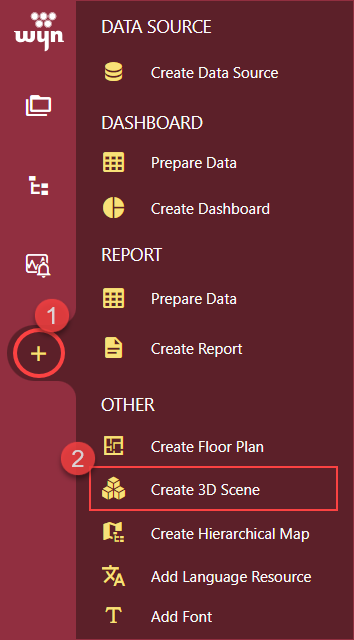
From the navigation bar click the + button and then, click the Create 3D Scene option.
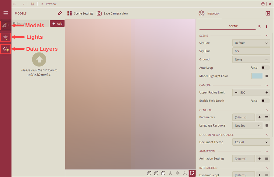
The 3D Scene Designer page will appear on your screen. 3D Scene Designer is divided into three sections - Models, Lights, and Data Layers as explained below.
Models
The Models section of the 3D Scene Explorer lists all the items of the 3D Scene.
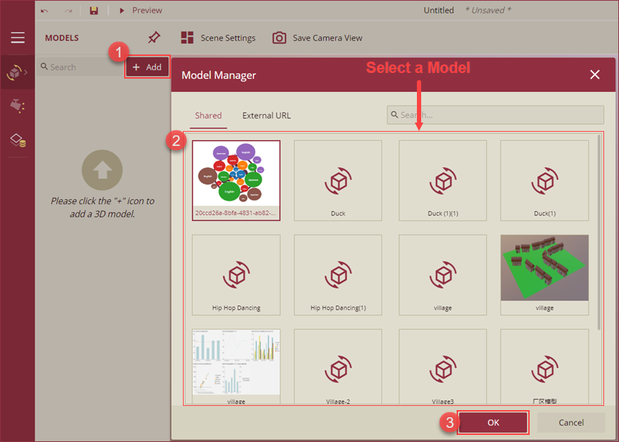
i) You can add new models to the 3D Scene using the + Add button. On clicking the + Add button, the Model Manager popup will appear on your screen. Add shared or external URL-based models to the 3D Scene. Simply select the model and click the OK button to add the model to the model list.
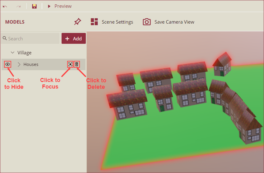
ii) Select model will be added to the scene designer. You can hide, delete, or focus on one element of the scene using the Hide, Focus, and Delete options on hover.
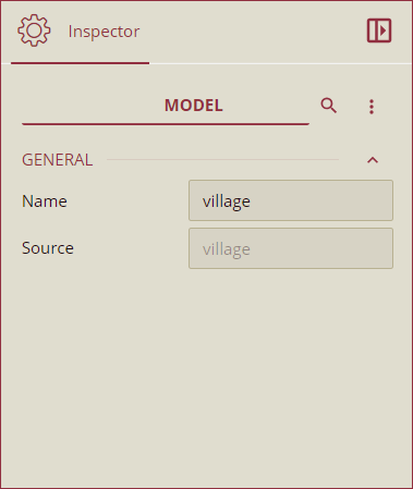
iii) The model information will appear on the Inspector panel where you can see the model name and source. For shared models, the name of the model appears in the Source and for the external URL-based models, the URL of the model.
iii) You can also add a 3D model to Wyn Enterprise using the Upload feature. Ensure that the 3D model file is in GLB format.
Note: For a better experience of the 3D model, when uploading keep the GLB file to less than 250MB.
Lights
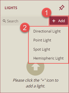
The lights section of the 3D Scene Explorer lists all the available light options. A default light with an intensity of 1 is added when initializing the 3D Scene. You can add the light options using the + Add button. The available light options are Directional Light, Point Light, and Spot Light as explained below.
Directional Light: Directional lights are used as a distant source of light that hits all the objects in a 3D Scene from the same angle regardless of the object's position.
Point Light: Point Light sources are the light sources used to produce a uniform beam of light with the illumination scattered in all directions. Point Light sources are also known as omnidirectional lights.
Spot Light: Spot Light sources are generally used for artificial light sources such as flashlights, headlights, and searchlights. The moving spotlight will illuminate a small area of the scene only.
Hemispheric Light: Hemispheric Light source are generally used to stimulate the ambient environment light.
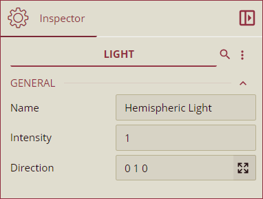
You can modify the name, intensity, and direction of the selected Light from the Inspector Panel.
Data Layers
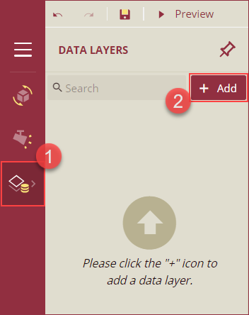
Data Layers are used to display the data related to the model objects of the 3D Scene. Follow the below instructions to add data layers to your 3D scene,
i) From the navigation bar, navigate to the Data Layers tab and click the + Add button.
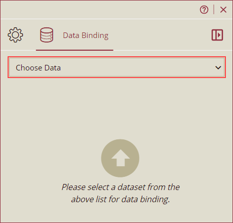
ii) From the Data Binding panel on the right side of your screen, select a dataset from the Choose Dataset dropdown.
iii) Now, drag and drop the dataset fields onto the Value and Mesh Name data containers.
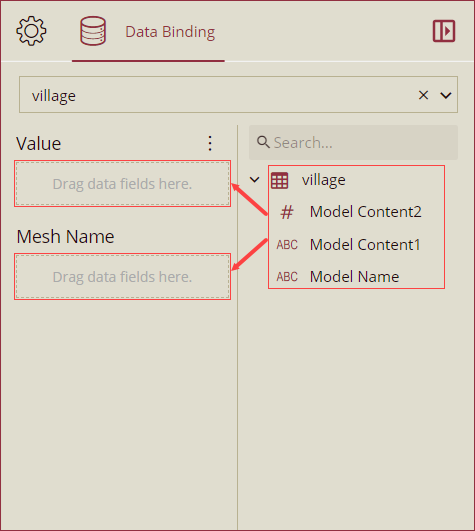
Value: Value is used to display the values of the count or sum of the data fields.
Mesh Name: Mesh Name is used to bind the 3D object of the scene with data labels.
Note: In case, the data attribute settings conflict with the data layer style, rich text customization will have the highest priority.
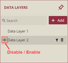
iv) Data layers will now appear on your scene designer under the Models section. You can hide the data layers using the hide icon next to the data layer name. In case a data layer is disabled, the tooltip will always be hidden and the mesh will not support mouse action or auto loop.
See the Data Layer Properties section for information on the Inspector Panel properties of Data Layers.
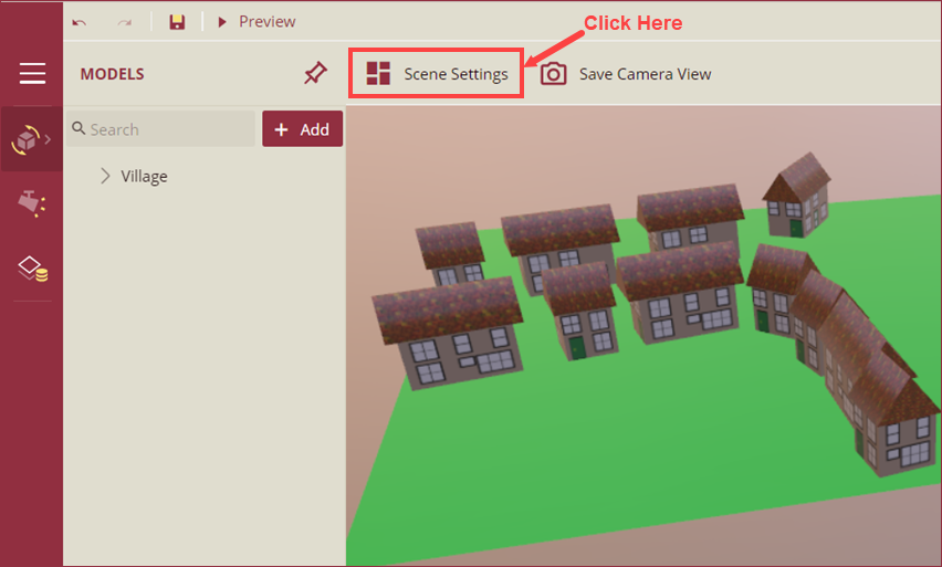
On successfully adding the models, lights, and data layers you can now modify the scene settings using the Scene Settings button on the 3D Scene Designer page. The scene settings are explained in the Scene Settings section below.
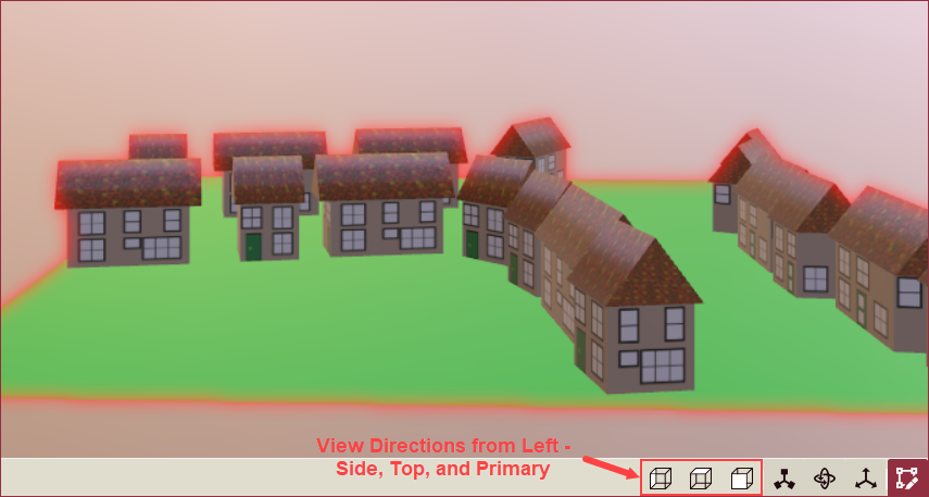
To modify the view direction of the scene, use the Designer Status Bar at the bottom of the scene designer. The three view options are explained below,
Side View: Used to switch the camera perspective to the side of the object.
Top View: Used to switch the camera perspective to the top of the object.
Primary View: Used to switch the camera perspective to the front of the object.
You can also use the Designer Status Bar to modify the position, rotation, and scale of the selected mesh. The selected mesh mode options are described below,
Position: Used to adjust the x, y, and z coordinates of the selected mesh. You can fine-tune the placement of a chosen mesh in only one direction at any given time.
Rotation: Used to rotate a selected mesh using the spherical coordinates. You can rotate a chosen mesh in only one direction at any given time.
Scale: Used to adjust the size of the selected mesh. You can zoom a selected mesh in only one direction at any given time.
Highlighting: Used to highlight the selected node of the scene. By default, the highlight is enabled.
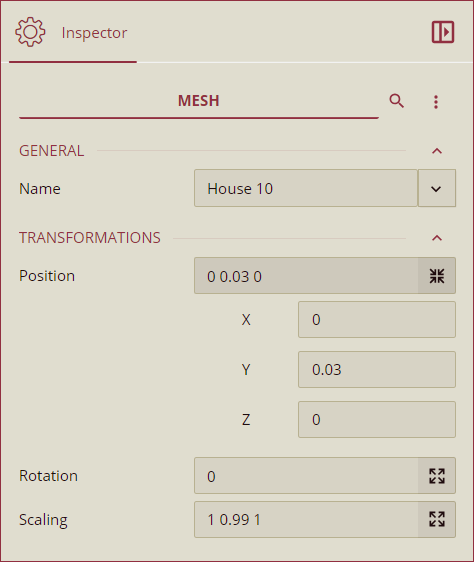
You can also use the Inspector Panel to modify the position, rotation, and scale of any mesh. Simply click the mesh and change the values under the Transformation section in the Inspector Panel.
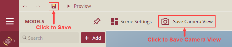
Use the save button on the top left corner of the scene designer to save the 3D Scene. You can also save the camera view of the scene to start editing the scene from the same position using the Save Camera View button.
You can view the created 3D Scene from the Document Types tab on the Resource Portal.
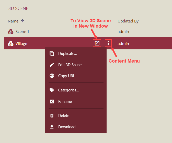
i) Navigate to the Document Types tab, click the 3D Scene option and the list of 3D scenes will appear.
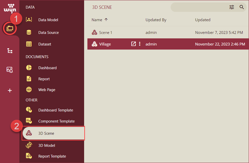
ii) You can view the 3D scene using the View 3D Scene in new window button. You can also duplicate, edit, copy URLs and categories, rename, delete, and download the 3D scene using the context menu.
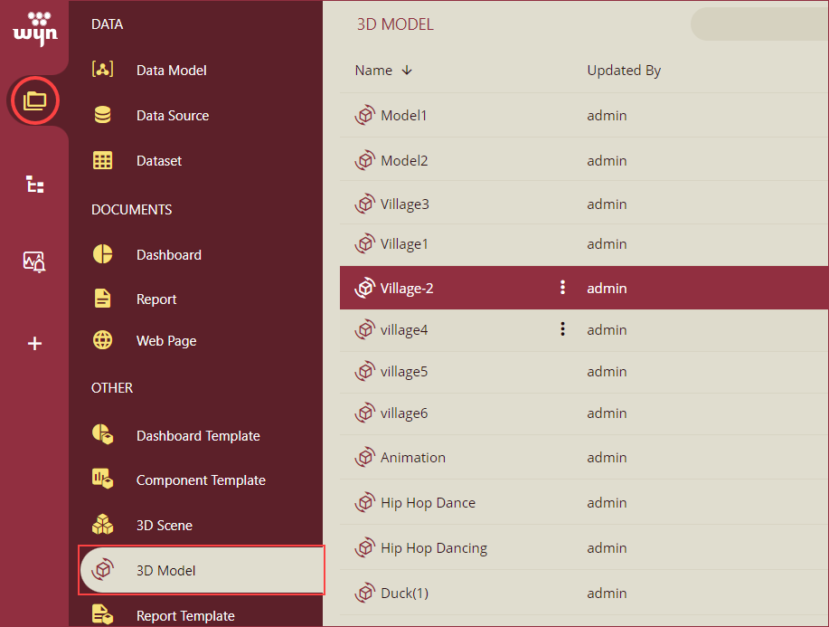
3D models added to Wyn Enterprise are listed in the 3D Model tab of the Document Types section.
Scene Settings
Listed below are the inspector panel properties of a 3D Scene,
SCENE
Option | Description |
|---|---|
Sky Box | To change the sky background of a 3D Scene, select an option from the dropdown. The available options are Default, Studio, Sky, Lilienstien, CapeHill, Wastelands Cloud Pure Sky, Custom URL, and None. By default, the Default option is selected.
|
Sky Blur | To control the blurriness of the sky background, add a value greater than 0 in the input box. 0.5 is the default value. |
Ground | Select an option from None or Grid Ground from the dropdown to set the ground background of the scene. By default, the None option is selected. - Grid Ground: Using the Grid Ground option you can select a geometrical shape to display the grids in the ground. Select a geometry from the Grid Ground option that appears on selecting the Grid Ground option in the Ground dropdown. - Background Color: Select a background color for the ground. - Line Color: Select the color of the grid line using this option. |
Model Highlight Color | Set a color to display for the highlighted model object. |
AUTO LOOP SETTINGS
Option | Description |
|---|---|
Auto Loop | To enable the auto loop of the camera set the Auto Loop option to True. By default, the value of Auto Loop is set as False. |
Highlight Color | Select the highlight color for node or mesh using this property. |
Camera Alpha | Set the angle ratio of the alpha camera using this property. |
Camera Beta | Set the angle ratio of the beta camera using this property. The value of the Camera Beta property can range from 0.01 to 1.57 (2/π). |
Camera Distance | Set the distance of the camera from the node or mesh using this property. |
Move Time (second) | Set a move time of the camera (in seconds) using this property. |
Stay Time (second) | Set the stay time of the camera using this property. |
CAMERA
Option | Description |
|---|---|
Upper Alpha Limit | Set the upper alpha limit of the camera using this property. |
Lower Alpha Limit | Set the lower alpha limit of the camera using this property. |
Upper Beta Limit | Set the upper beta limit of the camera using this property. The default value is 1.57. |
Lower Beta Limit | Set the lower beta limit of the camera using this property. The default value is 0.01. |
Upper Distance Limit | Set the upper distance limit of the camera using this property. The default value is 500. |
Lower Distance Limit | Set the lower distance limit of the camera using this property. The default value is 0. |
Enable Field Depth | To enable the camera depth of the field effect set the Enable Field Depth property to True. By default, the value is set to False. On enabling the field depth, the following options appear in the panel, Focus Distance: Set the focus distance of the camera using the Focus Distance option. Aperture Value: Set the aperture coefficient value of the camera using the Aperture Value option. Blur Level: Set the ambiguity level of the camera using the Blur Level dropdown. The available options are Low, Medium, and Hight. |
GENERAL
Option | Description |
|---|---|
Parameters | Add parameters to the 3D Scene using the + (Add Item) button. You can use the parameters to add calculated columns and model parameters. |
Global Filters | Add global filters to the scene using this property. |
Language Resource | To set a language resource select a resource from the dropdown. See the Language Resource help doc for more information. |
DOCUMENT APPEARANCE
Option | Description |
|---|---|
Document Theme | To change the theme of the 3D scene, select a theme from the Document Theme dropdown. The font color, font size, background, etc. will be affected when changing the document theme. |
ANIMATION
Option | Description |
|---|---|
Animation Settings | To manage the execution settings of animations designed in the 3D scene, click the + button and set the Name, Scene Animation, Invoked Event Type, Start Time, and Is Loop options on the Animation Setting popup. |
INTERACTION
Option | Description |
|---|---|
Dynamic Script | To embed a user code in the 3D scene click the + button and add the code in the Dynamic Script Setting popup. Wyn Enterprise uses Babylon.js to create dynamic scripts for a 3D scene. The Dynamic Script Setting popup items are described below, - Script Name: Name the dynamic script here. - Invoked Event Type: Select an option from the dropdown to invoke an event type. The following options are available; - Scene Loaded - Data View Change - Manual |
SPECIAL EFFECTS
Option | Description |
|---|---|
Particle | To enable particle effect in the 3D scene, set this option to True. By default, the value is set to False. |
Soaring Line | To enable the soaring line effect in the 3D scene, set this option to True. By default, the value is set to False. |
ANTI-ALIASING
Option | Description |
|---|---|
Enable MSAA | To disable MSAA (MicroSoft Active Accessibility) scheme, set the property to False. By default, the value is set to True. |
Enable FXAA | To enable the FXAA (Fast Approximate Anti-Aliasing) scheme, set the property to True. By default, the value is set to False. |
Data Layer Properties
MODEL LABEL
Option | Description |
|---|---|
Name | Use this property to change the name of the selected data layer. |
Display Mode | Select a display mode for the data layer using the dropdown. The available options are Always, Click, Hover, and Hidden. |
Font Setting | Set the font family, size, color, weight, and style of the model labels using this property. |
Background Color | Use this property to change the background color of the data labels. |
Background Image | Use this property to set a background image for the data labels. |
Border Color | Use this property to set the border color of the data labels. |
Border Radius | Use this property to set the corner radius of the data label borders. |
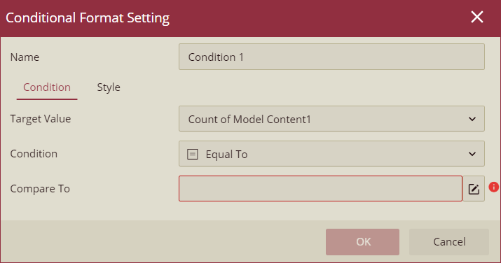
Conditional Formatting | Use this property to set the conditional formatting with conditions and styles to the data labels. |
INTERACTION
Option | Description |
|---|---|
Auto Refresh | Select an option from the dropdown to set the auto refreshing of the data labels. The available options are None, Polling, and Real Time. |
LAYOUT
Option | Description |
|---|---|
Size | Use this property to set the size of the data labels to automatic and fixed using the dropdown. |
Text Padding | Use this property to set the padding of the data label text. |
Vertical Offset | Use this property to set the vertical offset of the data labels. |
DATA VISUALIZATION
Option | Description |
|---|---|
Include All Dimensions | To include all dimension of the data labels, set the Include All Dimensions to True. By default, this property is set as False. |
Show Null As | Set the content to display in place of null data in the data labels using this property. |
Show Blank As | Set the content to display in place of blank data in the data labels using this property. |